この記事は、こういった声をサポートしていきます!
Arduino初心者歓迎シリーズ:機器導入、文法編、実践①、実践②、実践③、実践④(今ここ)
・Arduinoやってみたいけど、よくわかんないや!
・順番に手取り足取り教えてほしい!
今回は温湿度センサDHT11を使ってみようと思います。
このページで学べること
温湿度センサが使えれば、寒くなったら暖房つける、乾燥してたら加湿器つける、なんてことも可能になります。センサが人の五感に変わるものです。センサが使えるようになれば、マイコンからスイッチを押すってことができるってわけです。
別の回で、アナログ出力のLM35DZというのを使用した回があります。
今回のDHT11は温湿度が計測できるデジタル出力のセンサです。
アナログとデジタルの選択は、アナログのが玄人よりで単一機能(今回なら温度)を追求したい方。デジタルは一つのツールとして使いたい方。そんなイメージを私は持ってます。取り敢えずならデジタル出力のI2C通信タイプをオススメします。
温湿度センサDHT11
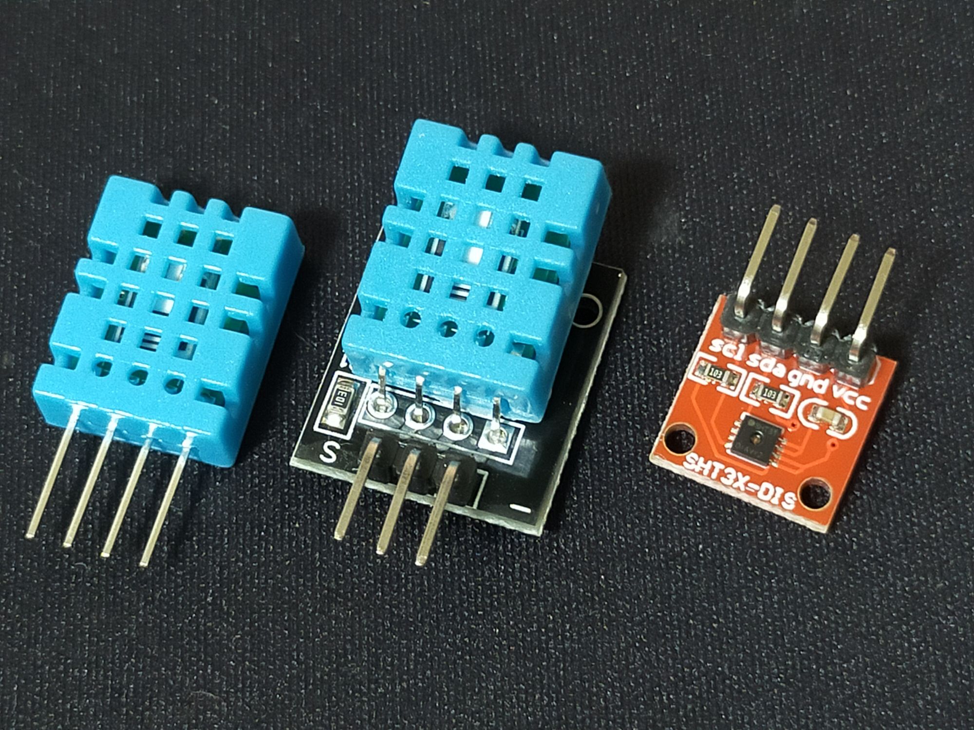
左から、DHT11の単品の状態、
真ん中が、初心者キットに入っていた3ピンとプルアップ抵抗付きの刺せばすぐ使える状態のもの
右が、別のSHT31という高機能版。DHT22に近い感じのもの。
値段は、高機能ほど高いです。売る製品を作る分には余分なコストですが、DIYレベルでは自分の懐具合。仕様をぱっと見比べてみると、少しだけ違う項目があります。温度の範囲と精度です。
◆DHT11の主な仕様
・電源電圧:Typ5V(3.3V~5.5V)
・通信方式:シリアル単線(1-wireライク)通信
・測定レンジと測定精度
温度:-20℃~+60℃、±2℃(@25℃)
相対湿度:5%~95%、±5%(@25℃)
・反応時間(τ63%):20秒[温度]、6秒[湿度]
・データビット数:8ビット(温度、湿度ともに)
・消費電流:0.3mA(測定時)
◆DHT22(AM2302)の主な仕様
・電源電圧:Typ5V(3.5V~5.5V)
・通信方式:シリアル単線(1-wireライク)通信
・測定レンジと測定精度
温度:-40℃~+80℃、±0.5℃(@25℃)
相対湿度:0%~99.9%、±2%(@25℃)
・反応時間(τ63%):10秒[温度]、5秒[湿度]
・データビット数:16ビット(温度、湿度ともに)
・消費電流:0.5mA(測定時)
◆SHT31の主な仕様
・電源電圧:Typ3.3V(2.4V~5.5V)
・通信方式:I2C(最大1MHz)
・測定レンジと測定精度
温度:-40℃~+125℃、±0.3℃(@0℃~90℃)
相対湿度:0%~100%、±2%(@0℃~90℃)
・反応時間(τ63%):2秒[温度]、8秒[湿度]
・データビット数:16ビット(温度、湿度ともに)
・消費電流:800µA(測定時)
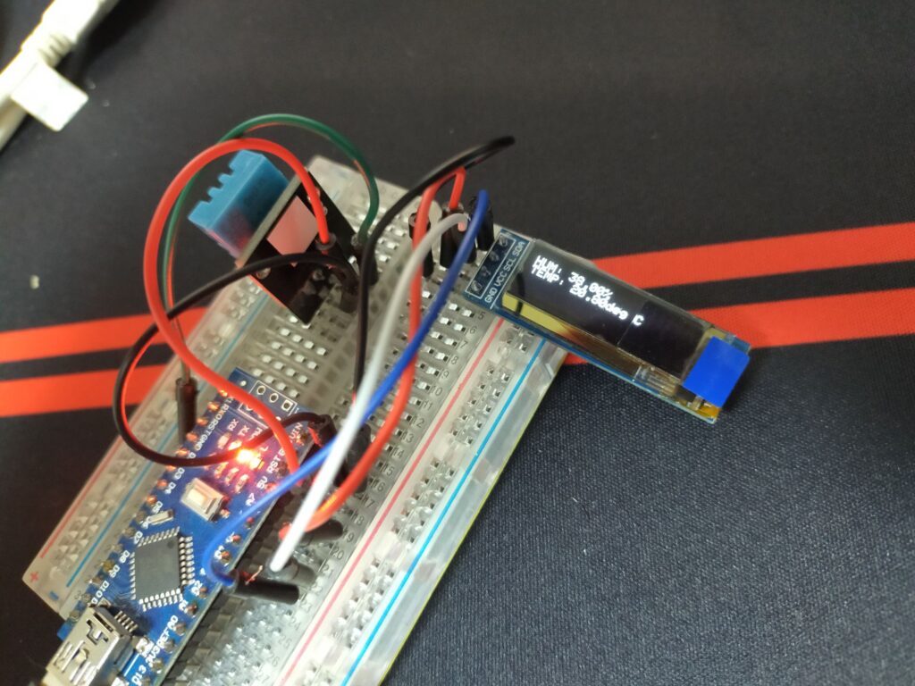
DHT11接続
DHTのライブラリのサンプルを使っていきます。
DHT11のデータピンを、Arduinoのデジタルピン2に。
ライブラリ準備
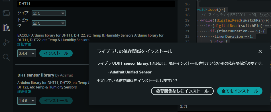
ライブラリマネージャで「DHT11」を検索。色々と出ますが、Adafruitの物を使っていきましょう。
どれでも使えればいいのですが、どれにしよっかなーと思ったら、Adafruitの使っておけば困らないと思います。不足してるのあるよとメッセでたら、「全てをインストール」選択。

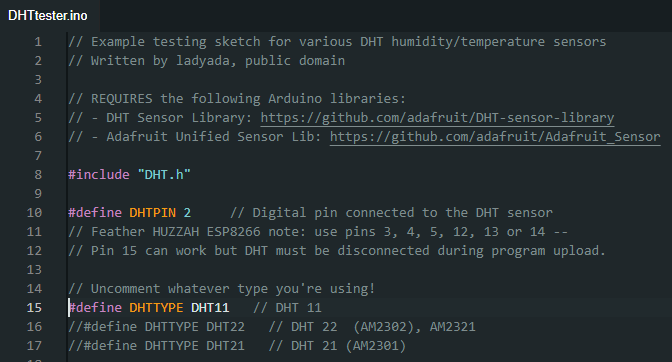
10行目にデフォルトでつなぐピンが記載してあります。変更したいときはここ変えてください。
15行目のDHT11をアンコメントして、16行目のDHT22をコメントアウト。
// Example testing sketch for various DHT humidity/temperature sensors
// Written by ladyada, public domain
// REQUIRES the following Arduino libraries:
// - DHT Sensor Library: https://github.com/adafruit/DHT-sensor-library
// - Adafruit Unified Sensor Lib: https://github.com/adafruit/Adafruit_Sensor
#include "DHT.h"
#define DHTPIN 2     // Digital pin connected to the DHT sensor
// Feather HUZZAH ESP8266 note: use pins 3, 4, 5, 12, 13 or 14 --
// Pin 15 can work but DHT must be disconnected during program upload.
// Uncomment whatever type you're using!
#define DHTTYPE DHT11   // DHT 11
//#define DHTTYPE DHT22   // DHT 22  (AM2302), AM2321
//#define DHTTYPE DHT21   // DHT 21 (AM2301)
// Connect pin 1 (on the left) of the sensor to +5V
// NOTE: If using a board with 3.3V logic like an Arduino Due connect pin 1
// to 3.3V instead of 5V!
// Connect pin 2 of the sensor to whatever your DHTPIN is
// Connect pin 3 (on the right) of the sensor to GROUND (if your sensor has 3 pins)
// Connect pin 4 (on the right) of the sensor to GROUND and leave the pin 3 EMPTY (if your sensor has 4 pins)
// Connect a 10K resistor from pin 2 (data) to pin 1 (power) of the sensor
// Initialize DHT sensor.
// Note that older versions of this library took an optional third parameter to
// tweak the timings for faster processors.  This parameter is no longer needed
// as the current DHT reading algorithm adjusts itself to work on faster procs.
DHT dht(DHTPIN, DHTTYPE);
void setup() {
  Serial.begin(9600);
  Serial.println(F("DHTxx test!"));
  dht.begin();
}
void loop() {
  // Wait a few seconds between measurements.
  delay(2000);
  // Reading temperature or humidity takes about 250 milliseconds!
  // Sensor readings may also be up to 2 seconds 'old' (its a very slow sensor)
  float h = dht.readHumidity();
  // Read temperature as Celsius (the default)
  float t = dht.readTemperature();
  // Read temperature as Fahrenheit (isFahrenheit = true)
  float f = dht.readTemperature(true);
  // Check if any reads failed and exit early (to try again).
  if (isnan(h) || isnan(t) || isnan(f)) {
    Serial.println(F("Failed to read from DHT sensor!"));
    return;
  }
  // Compute heat index in Fahrenheit (the default)
  float hif = dht.computeHeatIndex(f, h);
  // Compute heat index in Celsius (isFahreheit = false)
  float hic = dht.computeHeatIndex(t, h, false);
  Serial.print(F("Humidity: "));
  Serial.print(h);
  Serial.print(F("%  Temperature: "));
  Serial.print(t);
  Serial.print(F("°C "));
  Serial.print(f);
  Serial.print(F("°F  Heat index: "));
  Serial.print(hic);
  Serial.print(F("°C "));
  Serial.print(hif);
  Serial.println(F("°F"));
}
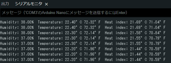
サンプルを動かすと、こんな感じで結果を表示されます。
液晶パネルに表示してみる
SSD1306のOLED液晶を使います。ライブラリはSSD1306 By Adafruitのもの。
サンプルプリグラムから、描画テストの部分を削除したものが、以下のもの。
/**************************************************************************
 This is an example for our Monochrome OLEDs based on SSD1306 drivers
 Pick one up today in the adafruit shop!
 ------> http://www.adafruit.com/category/63_98
 This example is for a 128x32 pixel display using I2C to communicate
 3 pins are required to interface (two I2C and one reset).
 Adafruit invests time and resources providing this open
 source code, please support Adafruit and open-source
 hardware by purchasing products from Adafruit!
 Written by Limor Fried/Ladyada for Adafruit Industries,
 with contributions from the open source community.
 BSD license, check license.txt for more information
 All text above, and the splash screen below must be
 included in any redistribution.
 **************************************************************************/
#include <SPI.h>
#include <Wire.h>
#include <Adafruit_GFX.h>
#include <Adafruit_SSD1306.h>
#define SCREEN_WIDTH 128 // OLED display width, in pixels
#define SCREEN_HEIGHT 32 // OLED display height, in pixels
// Declaration for an SSD1306 display connected to I2C (SDA, SCL pins)
// The pins for I2C are defined by the Wire-library.
// On an arduino UNO:       A4(SDA), A5(SCL)
// On an arduino MEGA 2560: 20(SDA), 21(SCL)
// On an arduino LEONARDO:   2(SDA),  3(SCL), ...
#define OLED_RESET     -1 // Reset pin # (or -1 if sharing Arduino reset pin)
#define SCREEN_ADDRESS 0x3C ///< See datasheet for Address; 0x3D for 128x64, 0x3C for 128x32
Adafruit_SSD1306 display(SCREEN_WIDTH, SCREEN_HEIGHT, &Wire, OLED_RESET);
#define NUMFLAKES     10 // Number of snowflakes in the animation example
#define LOGO_HEIGHT   16
#define LOGO_WIDTH    16
static const unsigned char PROGMEM logo_bmp[] =
{ 0b00000000, 0b11000000,
  0b00000001, 0b11000000,
  0b00000001, 0b11000000,
  0b00000011, 0b11100000,
  0b11110011, 0b11100000,
  0b11111110, 0b11111000,
  0b01111110, 0b11111111,
  0b00110011, 0b10011111,
  0b00011111, 0b11111100,
  0b00001101, 0b01110000,
  0b00011011, 0b10100000,
  0b00111111, 0b11100000,
  0b00111111, 0b11110000,
  0b01111100, 0b11110000,
  0b01110000, 0b01110000,
  0b00000000, 0b00110000 };
void setup() {
  Serial.begin(9600);
  // SSD1306_SWITCHCAPVCC = generate display voltage from 3.3V internally
  if(!display.begin(SSD1306_SWITCHCAPVCC, SCREEN_ADDRESS)) {
    Serial.println(F("SSD1306 allocation failed"));
    for(;;); // Don't proceed, loop forever
  }
  // Show initial display buffer contents on the screen --
  // the library initializes this with an Adafruit splash screen.
  display.display();
  delay(2000); // Pause for 2 seconds
  // Clear the buffer
  display.clearDisplay();
  // Draw a single pixel in white
  display.drawPixel(10, 10, SSD1306_WHITE);
  // Show the display buffer on the screen. You MUST call display() after
  // drawing commands to make them visible on screen!
  display.display();
  delay(2000);
  // display.display() is NOT necessary after every single drawing command,
  // unless that's what you want...rather, you can batch up a bunch of
  // drawing operations and then update the screen all at once by calling
  // display.display(). These examples demonstrate both approaches...
}
void loop() {
  display.clearDisplay();

}
上記のプログラムを作動させたもの。
文字数が足らないので、表示する内容を割愛しています。
こんな感じで、組み合わせていけば、色々と作れます。
おわりに
いかがだったでしょうか。
ライブラリの中身を、しっかり理解しようとすると難解ですが、
DIYレベルで使う分には、そこまでしなくても良いと私は思います。
使えるようになって、理解を深める必要があれば、ライブラリの中身とデータシート突き合わせて理解していけばいいと思います。
それではお疲れ様でした

コメント